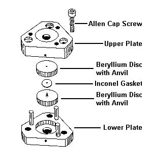
MB-SERIES
MERRILL-BASSETT TYPE DIAMOND CELL
Specifications:
|
The triangular shaped instrument, with the corners rounded, is
3 cm from the base of the triangle to the center of the curvature. The
thickness, with the diamonds in place, is 1.5 cm. The weight of the cell
with mounting bracket is 85 grams. The beryllium discs are 12.5 mm
in diameter and 3 mm thick; the diameter of the opening is 1 mm. Each
Type I diamond, with 16 pavilion facets, weighs approximately 1/6 carat
(1 carat = .20 g) and has a pressure bearing surface of 0.6 mm. Type
IIa anvils are used with IR.
This diamond cell has been assembled with two diamonds each weighing
approximately .20 carats with 0.6 mm culets or pressure bearing surfaces.
The anvils are attached to beryllium discs with epoxy cement unless
annealed stainless steel discs are requested.
|
|
|
The alignment and the parallelism have been completed by
H.P.D.O., Inc.
prior to shipping, therefore simply position the red markings when
loading your sample. Also, check the opposition and the parallelism under
a low power microscope consistently.
Diamond is
the hardest and least compressible material formed in nature, however diamond
will easily scratch diamond. To avoid damaging the diamond anvils certain
precautions must be observed. Keep a piece of paper between the anvils
when the instrument is not in use. Care must be taken when assembling the
cell to prevent the damage of the diamonds.
CAUTION:
DO NOT DEVELOP PRESSURE ON THE BARE DIAMOND ANVIL SURFACES.
The working
surface can be cleaned by wiping with a Chem-Wipe or other lint free tissue.
Solvents such as acetone or alcohol are used to wipe the anvil faces.
WARNING:
Excessive contact of solvents to the epoxy and glue will loosen the
bonding of the anvil to its mount.
The back side
of the anvils are cleaned by a sharpened toothpick. This procedure may
require several tries. A small needle is then used to remove the toothpick
debris.
Although a
pre-drilled gasket without indentation works fine as well, a pre-indented
gasket is recommended before a hole is drilled. Inconel, a metal foil 0.01"
thick, is supplied as gasket material. Any burrs around the hole should
be removed with a tip needle or a micro drill bit. The sample, usually a
100 micron die or less, with a pressure calibrant and pressure transmitting
medium is sealed by tightening three Allen cap screws. In order to maintain
the alignment and the parallelism of the anvils during the change of each
pressures, it is very important to monitor the thickness for the cell. A
micrometer can then be used. It is also a common phenomenon that the hole
will wander around under pressures; which might result in the failure of the
chamber seal if the pressure is not evenly applied to the diamond anvils.
Hence, it is always a good idea to re-exam your sample under a microscope
each time you have the pressure changed. The pressure range of this instrument
is about 100 kbars. The pressure increase is very sensitive with the squeeze
of the cell. Therefore, a good sense of very fine adjustment is necessary
when tightening three screws sequentially.
Also be aware
that the indented gasket won't return to the previous thickness after routinely
altering the pressures.
INSTRUCTIONS
The Merrill-Basset
type diamond anvil cell can be used to study physical properties of liquid
or solid samples under measurable pressure conditions.
CAUTION: DO NOT DEVELOP PRESSURE ON THE BARE DIAMOND ANVIL SURFACES.
Store the instrument
with a piece of cardboard between the two diamond anvils to prevent abrasions.
Anvils should be inspected before and after each use.
CLEANING THE ANVILS
The anvils
can be cleaned by wiping acetone or alcohol across the working surfaces
using tissue paper twisted into a pointed tip. Do not let the solvent come
into contact with the epoxy as it will eventually loosen the bond holding
the diamond to its mount. The working surfaces can also be cleaned by scraping
with a razor blade or with a needle. The undersides of the diamond anvils
are cleaned by scrubbing with a round toothpick or placing a drop of acetone
into the aperture if necessary.
HIGH PRESSURE STUDIES:
-
Clean the two diamond anvils as instructed above.
- Observing parallelism:
Align the red markings and assemble two triangular plates carefully
with fingers. Insert three Allen cap screws (#10-32) into the instrument
and turn until firm. Do not apply pressure on anvils yet. Observe the
fringe pattern with transmitted white light under magnification. (Pressure
calibrants such as ruby chips should be distributed evenly around
the sample for monitoring hydrostatic pressure conditions.) Carefully manipulate
the three Allen cap screws until only one light fringe is seen, showing
the parallelism of the diamond anvils.
- Measure and record the height of the
three sides of the instrument with a micrometer for future reference
in maintaining parallelism.
- Slowly disassemble the instrument.
- Gasket preparation:
A pre-indented gasket is recommended prior to making the sample
chamber hole. Make alignment markings on the gasket and the diamond
cell with wax or nail polish for future reference when positioning
the gasket (the rounded rectangular gasket, ½"x7/32"x0.01", and
a spacer secured by a #2-56 screw are provided.) Indent the gasket to
half its thickness, then drill a hole as close to the center of the indentation
as possible. Remove any rough edges (burrs) around the hole with a rat-tail
file or a micro drill bit. If a pre-drilled gasket is used, position
the hole as close to the center of the culet as possible. Then indent
the gasket and clean any rough edges with #78, #79 or #80 drill bits.
- Sample preparation:
Cut soft samples into small pieces (e.g. 50 microns die). Harder
samples may be polished with fine grit sandpaper and reduced by using
a sharpened needle.
- Loading sample:
The rounded rectangular gasket is centered on the lower anvil
and held in position by a screw. Note previous alignment markings.
- Level the lower support and load the
sample, pressure calibrate (e.g. ruby chips) and pressure transmitting
medium (e.g. liquid argon) under magnification1. Several
attempts may be needed when performing this step. After completing this
step, proceed to step 9 immediately.
- Assemble the instrument and tighten
the three Allen cap screws sequentially in very small increments until
a moderate amount of pressure is applied to the gasket. This procedure
is needed to ensure the pressure-transmitting medium has been successfully
loaded.
- Observe the chamber hole. Under pressure,
the hole will change shape slightly. However, if the hole is significantly
deformed, the instrument may have lost the pressure medium. if medium
loss is uncertain, apply more pressure by tightening the three Allen
screws and observing the sample hole for any changes. Begin the process
from step 1 if the pressure medium has been lost. Otherwise, proceed to
step 11.
- Measure and record the height again
as instructed in step 3. The parallelism can be maintained by comparing
these measurements with the data obtained earlier in step 3.
- Pressure calibration:
Ruby fluorescence can be used to calibrate the in-situ pressure.
The frequency shifts of the R1 and R2 lines
determine the pressure by using the following formula:
Pi = 380.8 x [(w
oi / wi)5 –
1] i = 1, 2
Where w
oi is the wavenumber in cm-1 corresponding
to ruby R1 and R2 lines at ambient pressure;
wi
is the wavenumber at the measured pressure. The pressure P is given
in GPa (1 GPa is approximately 10 kilobars). Light sources using an
argon ion laser from 488 nm and 514.5 nm lines are commonly used in
this technique.
- Record the current pressure.
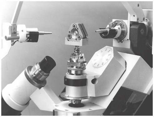
- X-ray studies only
: Attach the X-ray bracket supplied by
High Pressure Diamond Optics, Inc. to the diamond anvil cell with
two #2-56 screws. Position the instrument to the goniometer head.
Note that the diamond anvil cell should have come with beryllium disks
as diamond mounts to be used for X-ray studies.
- Proceed with the experiments.
- Altering Pressure:
The pressures can be repeatedly altered by tightening or loosening
the three Allen screws. Refer to steps 2, 3, and 11 for maintaining
parallelism. The chamber hole may shift under altered pressures. Turn
the Allen cap screw(s) to move the chamber hole toward the opposite
direction if the hole is off center to the culet. Notice that turning the
screws will change the pressure. Follow this step closely to avoid sample
failure.
- Calibrate the pressure according to
step 12, then continue experiments.
- Disassemble the cell by loosening the
screws sequentially in small increments. Store the diamond cell as
instructed.