Also see Bob Danielson's Horn Button Contact repair.
TR6 Horn Repair
Repairing a horn is a very simple process, but given how inexpensive new horns are, you may decide to just purchase a new one. At the time of writing this article (07 Oct 2008), a new horn that looks like the one pictured below can be purchased from The Roadster Factory for $29.95. However, for about $5.00 in parts, I repaired and restored what I hope is an original horn for my 1976 TR6.
If you need to diagnose the horn circuit, I suggest you purchase Dan Masters' excellent book, Triumph TR250-TR6 Electrical Maintenance Handbook. (Ordering info available here.)
Once you have determined that a malfunctioning horn is the problem, as opposed to a problem with wiring, switches, power, etc., this page can step you through the details of horn repair.
The horn shown on this page is the passenger side horn from my car. It is the "high" horn and it looks just like the horn on the driver's side of my car with the exception of an "H" on the inside of the horn's mouth (the opening of the horn where the sound comes out.) I assume the other horn has an "L" inside its mouth.Electrical Connections
 By following Dan Masters' troubleshooting flowchart, I determined that this
horn did not work. I removed the horn from the car and connected power to it
two ways, just for fun:
By following Dan Masters' troubleshooting flowchart, I determined that this
horn did not work. I removed the horn from the car and connected power to it
two ways, just for fun:
- I connected it to the leads that fed the working, driver's side horn. It
wouldn't sound when I pressed the horn button on my steering wheel.
- Then I tried connecting the suspect horn to my battery charger at the 2 Amp setting. The horn might have hummed a little.
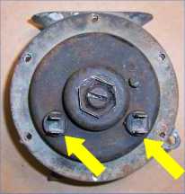
The horn's power terminals are indicated with yellow arrows in the photo at right. When connecting power to the horn, you connect positive to one terminal and negative to the other — it doesn't matter which polarity gets connected to which terminal. Each terminal has two spades and it doesn't matter which spade you use.
Other External Points of Interest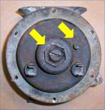 In the center of the horn, there is a slotted screw with a hexagonal stamped
metal "lock nut" around it. (Indicated by the leftmost yellow arrow in the
drawing at right.) This screw is used to adjust the noise the horn makes.
When making adjustments, adjust this screw first. If you want to read about
adjusting horns, scroll down to Getting the Darn Thing to Work: Turning
the Screw.
In the center of the horn, there is a slotted screw with a hexagonal stamped
metal "lock nut" around it. (Indicated by the leftmost yellow arrow in the
drawing at right.) This screw is used to adjust the noise the horn makes.
When making adjustments, adjust this screw first. If you want to read about
adjusting horns, scroll down to Getting the Darn Thing to Work: Turning
the Screw.
- To the right of the horn there is a bolt with a 1/4" head and a left-hand thread. (Indicated by the rightmost yellow arrow in the drawing at right.) In some references this is described as being a slotted screw. When making adjustments, adjust this bolt second.
Getting to Work
To get to work on my horn, I gave the screw and bolt a squirt of penetrating oil, removed the lock washer, and screwed/unscrewed the screw and bolt to loosen them from their frozen, rusted state.
I also drilled off the tops of all six rivets and then punched them out0 with a nail set and a hammer. Before drilling, I used a center punch to create a divot in the center of each rivet that kept my drill bit from wandering. The rivets looked like aluminum and drilling was no problem at all.
Opening the HornHindsight is 20/20: Knowing what I know now, before drilling rivets I would mount a suspect horn in a vise, connect it to power, and twist the screw and bolt with impunity to see if I could get the horn to sound. From what I can tell, you can't hurt anything by twisting the screw or bolt too far and you might just dislodge a bit of corrosion that is causing something to fail. See the section Getting the Darn Thing to Work: Turning the Screw for a description of how to adjust these settings.
However, even if my horn was simply out of adjustment, given the failed state of the gaskets, an overhaul was worth it.
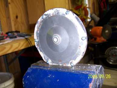
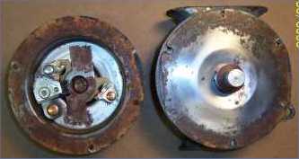 This
picture shows the top of the horn removed and flipped to the left. The
diaphragm of the horn is shown shining on the right. There is a metal
rod in the center of the diaphragm and there is a brown, non-conductive
washer fixed to the metal rod.
This
picture shows the top of the horn removed and flipped to the left. The
diaphragm of the horn is shown shining on the right. There is a metal
rod in the center of the diaphragm and there is a brown, non-conductive
washer fixed to the metal rod.
The brown crap around the rim of the top is (was) some kind of gasket. There is a great deal of rust around the edge of the diaphragm, clearly indicating that the gasket material failed.
If your horn looks like this, do not despair: I repaired the horn you are looking at.
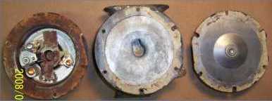 This
photo shows the diaphragm removed and flipped to the right. The hole in
the center of the bottom of the horn (the middle element in the photo at
right) is the opening to the resonating chamber which connects to the
horn's mouth via a short, spiral tunnel.
This
photo shows the diaphragm removed and flipped to the right. The hole in
the center of the bottom of the horn (the middle element in the photo at
right) is the opening to the resonating chamber which connects to the
horn's mouth via a short, spiral tunnel.
There isn't much you can do to the bottom or the diaphragm except clean the old gasket material off them, clear spider webs out of the resonating chamber in the bottom of the horn, and take as much rust off as you can with a wire brush.
Inside the Top of the Horn: Where the Fun Is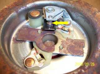 The
Brass Rivets: The power terminals on the outside of the top connect to these.
These rivets are at either end of a coil of wire which serves as an
electromagnet. Make sure there is continuity between these rivets. You can
visually inspect how the wire ends connect to each rivet.
The
Brass Rivets: The power terminals on the outside of the top connect to these.
These rivets are at either end of a coil of wire which serves as an
electromagnet. Make sure there is continuity between these rivets. You can
visually inspect how the wire ends connect to each rivet.
The Black Arm: This is a normally closed (NC) switch that is part of the electromagnetic coil circuit. The contacts on this switch are indicated by the yellow arrow at right.
Here is how the coil and the NC switch function together to cause the horn to sound:
- When power is applied to the terminals, the wire coil energizes and becomes an electromagnet. (Horn adjustment note: In the photo above, you can see the bottom of the big adjustment screw. It is peeking up from the hole in the center of the cap. It is this screw that becomes the magnet when the coil is energized. When you adjust this screw, you are affecting the electromagnet's pull on the diaphragm.)
- This magnet acts on the metal rod on the top of the diaphragm, causing the diaphragm to be pulled towards the top of the horn.
- As the diaphragm moves toward the top of the horn, that non-conductive washer on the diaphragm's rod pushes The Black Arm of the NC switch, causing it to open.
- When the NC switch opens, the electromagnet turns off, causing the diaphragm to snap away from the top of the horn.
- The non-conductive washer no longer holds the NC switch open, so the NC switch closes, and we are returned to step one.
It is the action of the diaphragm vibrating back-and-forth that creates the sounds waves you hear.
Points of Failure for a HornNow that you have seen how simple a horn is, you can see how simple it is to isolate a point of failure.
- Contacts: In my horn, I cleaned the contacts of the normally closed switch by pulling 600 grit sandpaper through them a few times. I think this solved my horn's problem; there was corrosion on those contacts that prohibited current from flowing sufficiently to energize the electromagnet to an extent that would flex the diaphragm.
- Coil: Another point of failure is a break in the long piece of wire that forms the electromagnet coil. You could solder the break or rewind the entire coil.
- Adjustment: A horn might simply fall out of adjustment, i.e., the big slotted screw and 1/4" bolt might not be set properly. Given how tight the adjustment screw and bolt were, this seems improbable to me, but it is worthwhile to explore this option before you drill rivets out.
 Getting the Darn Thing to Work:
Temporary Assembly
Once you clean the contacts and ensure continuity of the coil, it's time to see if you can get the horn to buzz.
Connect the diaphragm to the top using six #6 screws and nuts. You could include the bottom as part of this temporary assembly, but in the photo at right, you can see that I omitted the bottom. (You are looking at the bottom of the diaphragm.)
There is a photo disconnect between this photo and the next. The next photo is a staged shot to show how I applied power to the horn using my battery charger, held the power leads to keep them from falling off, and adjusted the screw -- all at the same time with only two hands!
Getting the Darn Thing to Work: Turning the Screw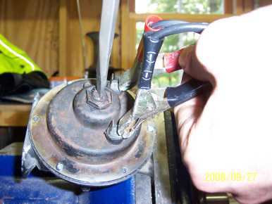 In
the photo at right, the hex nut is very loose. When you are exploring the
function of the slotted screw, you should simply remove the hex nut so you
can twist the slotted screw without having to worry about the hex nut falling
off.
In
the photo at right, the hex nut is very loose. When you are exploring the
function of the slotted screw, you should simply remove the hex nut so you
can twist the slotted screw without having to worry about the hex nut falling
off.
I've got power leads from my battery charger (feeding 2 Amps) connected to the power terminals. I'm holding them so they don't vibrate off and touch each other: when you get the horn to respond, it will vibrate a great deal.
Let's assume the slotted screw begins this process in a very screwed out state. As you screw the screw in, the horn will start to sound more and more until it assumes a very raspy tone at which point you will want to back the screw out. As you turn this screw in and out, it will be very obvious to you where the right position is.
I wore ear muffs during this operation.
Getting the Darn Thing to Work: Turning the 1/4" Bolt
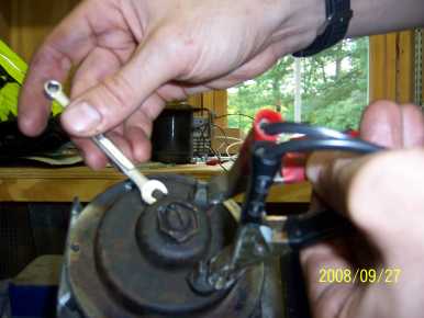 Once you've got the tone as clear and loud as you can with the screw, twist
the 1/4" bolt to refine the tone.
Once you've got the tone as clear and loud as you can with the screw, twist
the 1/4" bolt to refine the tone.
"Refine the tone" might seem like vague terminology, but once you start to adjust this bolt, you will see what I mean.
You can go back and forth between the screw and the bolt to hear how changing one affects the other. Adjusting the screw and bolt for a minute or two (literally) will enable you to find the perfect setting.
I wore ear muffs during this operation.
Once you get the horn to work, you'll know it is worth your time and money to purchase some materials for repair, fabricate a couple of gaskets, and proceed to final assembly.
Materials for Repair
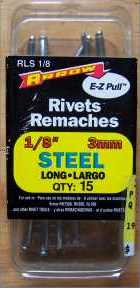
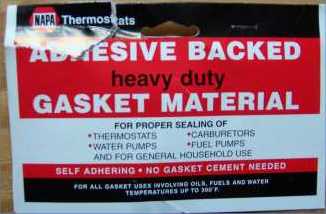
All you need to assemble your horn is some gasket material and pop rivets. Here are labels for what I bought. Total cost about $5.00.
Fabrication: Make Two Gaskets
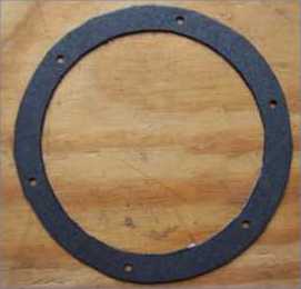 You'll need to make two circular gaskets, employing your 2nd grade
tracing and cutting skills. My kids have a 1/8" hole punch in their
art box that I used to punch the holes.
You'll need to make two circular gaskets, employing your 2nd grade
tracing and cutting skills. My kids have a 1/8" hole punch in their
art box that I used to punch the holes.
I picked this gasket material because it was the thinnest stuff the NAPA store had. It is adhesive on one side. I stuck the adhesive to flanges on the top and the bottom of the horn.
You should have enough gasket material left over to actually make a gasket for your thermostat or fuel pump, if need be.
Final Assembly- Insert #6 screws through all six holes and tighten them down.
- Admire the edges of your nice new gaskets as they sandwich the diaphragm.
- The addition of gasket material will change the setting of the slotted screw slightly, so you'll have to go through a final adjustment of the slotted screw and 1/4" bolt.
- Remember to tighten the hex lock nut.
- Remove every other screw and insert pop rivets.
- Remove the remaining screws and insert pop rivets.
- Connect the horn to your car, push the horn button, and listen to your TR6's jarring, two-tone horns.
Copyright © 2008 Scott A. Butler, All Rights Reserved